
There are two primary types of drivers for stepper motors, constant voltage drives (also referred to as L/R drives), and constant current drives (also referred to as chopper drives).
One difficulty with stepper motor operation is that the time constant (L/R) of the motor windings prevents current from increasing rapidly during pulses. This means that unless the voltage is very high, the current can never reach its full rated value, especially when the pulse rate is high (i.e. at high motor speeds). This limitation is governed by two equations:
Ohm’s Law:
![]()
Where:
I = current
V = voltage
R = resistance
Current rise and inductance relationship:
![]()
Where:
dI/dt = current rise time
L = inductance
In order to get high current – and therefore high torque – at high speeds, the voltage needs to be kept as high as possible and the inductance as low as possible. But in traditional L/R drives, the voltage must be kept low in order to keep the steady-state current from becoming excessive.
The value of L/R is the time constant, τe, which is the time it takes for the current to reach 63 percent (1 – 1/e) of its final value.
A chopper drive addresses the problem of obtaining high torque at high speed from a stepper motor by turning the output voltage to the motor on and off rapidly (aka “chopping”) to control the motor current. At each step of the motor, a very high voltage (typically eight times higher than the motor’s nominal voltage) is applied to the motor windings. This causes the current to rise rapidly, according to the relationship between current rise and inductance. It also allows higher current to be produced, according to Ohm’s law.
A constant, fixed frequency of voltage chopping – typically 20 kHz or higher (above the audible range) – varies the width of the output pulses. Winding impedance varies with motor speed, so at higher speeds (higher impedance in the windings), the voltage on-time is longer, which produces a larger pulse width, allowing the current to build to the proper level. At lower speeds (lower winding impedance), the voltage on-time is shorter, giving a smaller pulse width. This technique is also referred to as pulse width modulation (PWM).
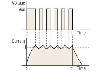
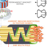
Image credit: Oriental Motor USA Corp.
Current in a chopper drive is regulated by a current-sensing resistor placed in series with each winding. As current increases, voltage develops across the resistor, and a comparator monitors this voltage level. At a predetermined reference voltage, the output voltage is turned off (chopped) until the next pulse takes place. In this way, current builds and declines as the voltage switches off and on, resulting in the proper average current per step cycle. This enables precise control of torque, regardless of variations in the power supply voltage. It also gives the shortest possible time for current build-up and decline.
Although a chopper drive requires additional electronics to monitor current in the windings and to control voltage switching, it allows a stepper motor to produce higher torque at higher speeds than a traditional L/R drive.
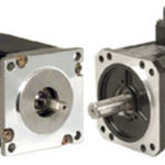
Feature image credit: Haydon Kerk Motion Solutions


Leave a Reply
You must be logged in to post a comment.