
Absolute encoders — whether rotary or linear — track the position of an axis by assigning a unique value to each position on the encoder, so that no matter where the axis being measured is located, its exact position can be determined. And because each position is uniquely identified, this holds true even if the encoder has been powered off and restarted — there’s no need to re-home the encoder upon power-up in order to determine its position.
For most absolute rotary encoders, resolution is defined in terms of bits, or binary words. The encoder disk is patterned with concentric tracks around its circumference (and a corresponding number of sensors — one for each track), and each track represents one bit of resolution.
To convert bits of resolution into the number of positions the encoder can detect with each shaft revolution, simply raise the number 2 to the power of the number of bits. For example, an 8 bit encoder would be able to measure 256 positions for each shaft revolution (28), and a 16 bit encoder would be able to measure 65,536 positions per revolution (216).
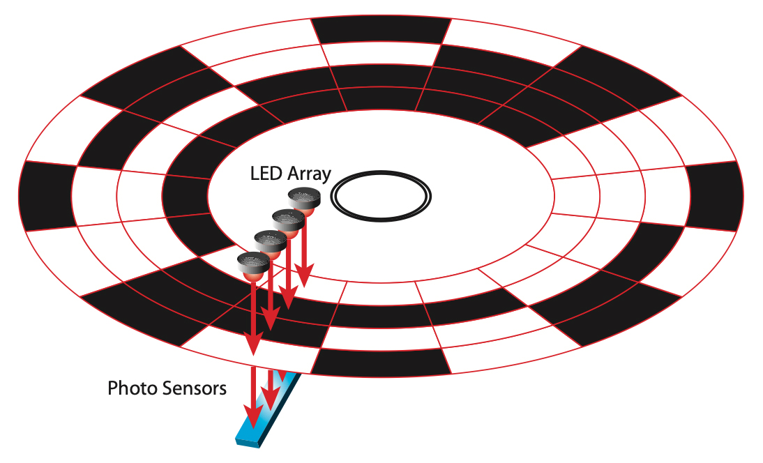
Image credit: US Digital
But what if the encoder makes more than one revolution during a measurement? The basic type of absolute rotary encoder — as described above — is referred to as a single-turn encoder, which uses one code disk. While single-turn encoders can track the position of an axis within one encoder revolution, the position values are repeated with each revolution, and the encoder has no way to determine how many revolutions have been completed. So applications such as winding and conveying — that move continuously in a single direction — or those that require a very long stroke before changing direction, will typically exceed a single encoder turn, and therefore, lose the ability to track absolute position.
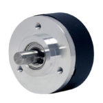
Another type of absolute rotary encoder — known as a multi-turn encoder — can track not only the position within one revolution, but also the number of revolutions the encoder makes, up to 4096 turns on typical designs. Multi-turn encoders come in several variations, including those that use multiple disks connected by gears and those that use electronic counters to track the number of turns. For those that use multiple, geared disks, the encoder’s total resolution is the sum of the resolution for all disks. So a multi-turn encoder that has a primary disk with 10 bits of resolution and a secondary disk with 8 bits of output will have a total resolution of 18 bits and will be able to measure 262,144 unique position values (218).
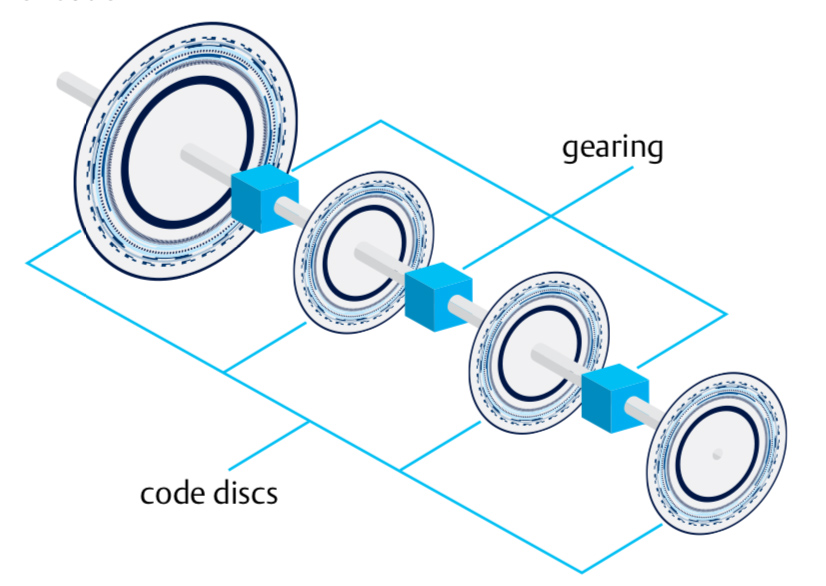
Image credit: Nidec
Binary versus Gray code
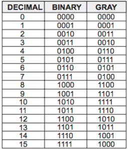
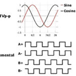
When encoder output is transmitted via parallel or serial interface (the other transmission option being via bus interface), the output is typically given in a modified form of binary code, referred to as Gray code. Standard binary code consists of a series of 1’s and 0’s, which change with each position, or step, of the encoder. But this presents a problem for data transmission, because some steps involve changes in more than one digit.
For example, from step 3 to step 4, binary code changes from 0011 to 0100, with three digits changing state. Because it is impossible for the digits to change at exactly the same time, the encoder could read the first two digits in one state, but by the time it reads the third and fourth digits, the state could have changed again, giving a mixed — and incorrect — position reading. Gray code avoids this problem by changing only one digit at each step.
Absolute linear encoders
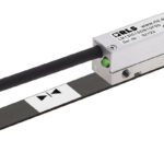
Absolute linear encoders also assign a unique value to each position, but in this case, the value is determined by the code pattern along the linear scale. The measuring units, which are detected by the encoder’s read head, are arranged in a specific pattern to provide a binary code that indicates the position along the length of the encoder. Resolution, then, is typically given by the smallest distance the encoder can measure — in microns (μm) or nanometers (nm) — rather than in bits.
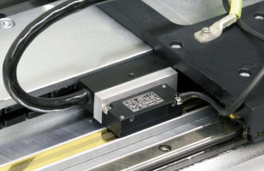
Image credit: Heidenhain


Leave a Reply
You must be logged in to post a comment.