• Skip to primary navigation
  • Skip to main content
  • Skip to primary sidebar
  • Skip to footer

Linear Motion Tips

Covering Linear Motion Systems, Components and Linear Motion Resources

  • New
    • Editor’s blog
    • Industry news
    • Motion Casebook
    • Video
  • Applications
  • Slides + guides
    • Ball + roller guides
    • Track roller (cam + wheel) guides
    • Crossed-roller slides
    • Linear bearings
    • Plastic + composite guides
  • Drives
    • Ball + lead + roller screws
    • Belt + chain drives for linear
    • Rack + pinion sets
  • Actuators
    • Ball + leadscrew driven
    • Belt + chain driven
    • Linear motors
    • Mini + piezo + voice coil
    • Rack + pinion driven
    • Rigid-chain actuators
  • Encoders + sensors (linear) + I/O
  • Stages + gantries
  • Suppliers

What’s the difference between module and diametral pitch for rack and pinion drives?

May 14, 2021 By Danielle Collins Leave a Comment

A helical tooth rack and pinion drive.
Image credit: Atlanta Drives

Gear sizes are typically specified by one of two designations: module or diametral pitch. While both specifications define the size of the gear teeth, module and diametral pitch are calculated differently, with module (sometimes referred to as metric pitch) being the metric sizing standard and diametrical pitch being the Imperial (inch) sizing method.


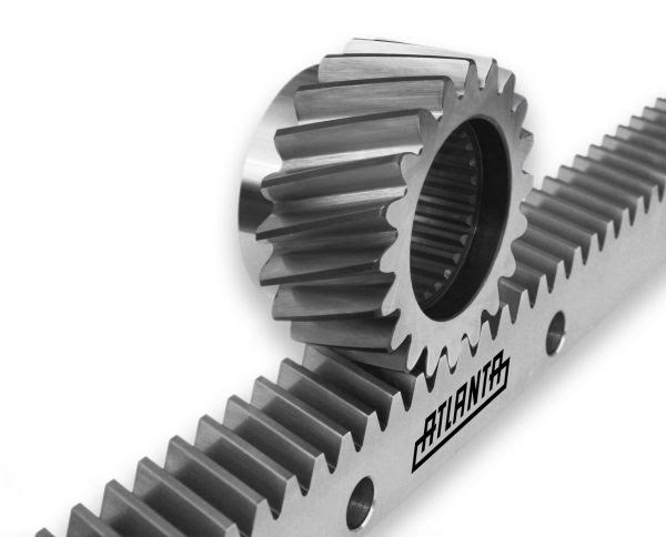
Standard modules for straight and helical gears are defined by ISO 54:1996 and indicate the amount of pitch diameter (or pitch length, in the case of a straight rack) that each tooth occupies. The larger the module, the larger the gear teeth and the overall gear.

difference between module and diametral pitch

m = module (mm)

d = pitch diameter or pitch length (mm)

n = number of teeth

Gear pitch circle and pitch diameter
Image credit: mit.edu

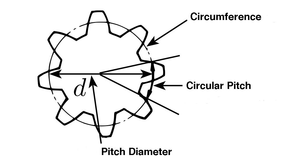
Module can also be found by dividing the circular pitch by pi (π).

module équation

m = module (mm)

p = circular pitch (mm)

Rack Module
The module of a gear can be found by dividing the pitch by pi (π).
Image credit: Kohara Gear Industry

To find the circular pitch of a gear, divide the circumference around the pitch circle (circumference = pi x pitch diameter) by the number of teeth.

circular pitch equation

p = circular pitch (mm)

d = pitch diameter (mm)

n = number of teeth

By removing the circular constant of pi (π), the module system simplifies the calculations for other gear parameters.


Diametral pitch, on the other hand, indicates the number of teeth per inch of pitch diameter. It’s important to note that tooth (and, therefore, gear) size varies inversely with the diametral pitch. In other words, a larger diametral pitch means there are more — and, therefore, smaller — teeth per inch of pitch diameter.

difference between module and diametral pitch

DP = diametral pitch (1/in)

n = number of teeth

d = pitch diameter or pitch length (in)

diametral pick rack
With 10 teeth per inch, this is a 10DP rack.
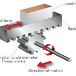
Image credit: R. K. Mobley

Because it’s based on Imperial units, diametral pitch is used primarily in the U.S. However, most high-precision rack and pinion drives — both within and outside of the U.S. — use module size designations.


Module and diametral pitch are inverses of one another and are related by the millimeter-to-inch conversion of 25.4, where:

difference between module and diametral pitch

DP = diametral pitch (in)

m = module (mm)

Although module and diametral pitch are similar, mating gears with different sizing schemes can’t be used together or directly interchanged. In other words, mating gears must have either the same module (for example, m2 pinion with m2 rack) or the same diametral pitch (for example, 12DP pinion with 12DP rack).


Note that these calculations are for rack and pinion drives with spur (straight) teeth. For versions with helical teeth, there are two measures of pitch (normal and transverse), and therefore, two versions of module and two versions of diametral pitch.

helical gear modules
Helical gears have both a normal pitch and a transverse pitch, leading to two measurements for module and two measurements for diametral pitch.
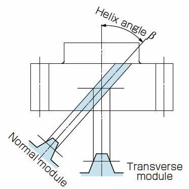
Image credit: QTC Metric Gears

You may also like:


  • Top 10 considerations when applying rack and pinion systems

  • How to size a rack-and-pinion system for a precision motion…
  • thrust actuator
    Which type of linear actuator is best for thrust forces?
  • rack and roller pinion
    How does a rack and roller pinion work?

  • Linear actuators: belt driven vs. rack and pinion driven

Filed Under: FAQs + basics, Featured, Rack + pinion driven, Rack + pinion sets

Reader Interactions

Leave a Reply

You must be logged in to post a comment.

Primary Sidebar

DESIGN GUIDE LIBRARY

“motion
Subscribe Today

RSS Featured White Papers

  • Evaluating actuators for washdown in food & beverage applications
  • Identifying Best-Value Linear Motion Technologies
  • Introduction to accuracy and repeatability in linear motion systems

RSS Motion Control Tips

  • New servo and motion bundles simplify machine integration
  • Kit encoders now included in product finder portal from POSITAL
  • Mitsubishi Electric Automation launches new online request-for-quote tool
  • ABB launches new app for rapid, remote tech support
  • ABB opens global innovation and training campus for machine automation at B&R in Austria

Footer

Linear Motion Tips

Design World Network

Design World Online
The Robot Report
Coupling Tips
Motion Control Tips
Bearing Tips
Fastener Engineering

Linear Motion Tips

Subscribe to our newsletter
Advertise with us
Contact us
About us

Follow us on TwitterAdd us on FacebookAdd us on LinkedInAdd us on YouTubeAdd us on Instagram

Copyright © 2022 · WTWH Media LLC and its licensors. All rights reserved.
The material on this site may not be reproduced, distributed, transmitted, cached or otherwise used, except with the prior written permission of WTWH Media.

Privacy Policy