• Skip to primary navigation
  • Skip to main content
  • Skip to primary sidebar
  • Skip to footer

Linear Motion Tips

Covering Linear Motion Systems, Components and Linear Motion Resources

  • New
    • Editor’s blog
    • Industry news
    • Motion Casebook
    • Video
  • Applications
  • Slides + guides
    • Ball + roller guides
    • Track roller (cam + wheel) guides
    • Crossed-roller slides
    • Linear bearings
    • Plastic + composite guides
  • Drives
    • Ball + lead + roller screws
    • Belt + chain drives for linear
    • Rack + pinion sets
  • Actuators
    • Ball + leadscrew driven
    • Belt + chain driven
    • Linear motors
    • Mini + piezo + voice coil
    • Rack + pinion driven
    • Rigid-chain actuators
  • Encoders + sensors (linear) + I/O
  • Stages + gantries
  • Suppliers

What are goniometer stages and where are they used?

September 5, 2018 By Danielle Collins 1 Comment

The term “goniometer” can refer to a type of device that measures angles or to a device that rotates objects to a precise angular position. The former type, for measuring angles, is widely used in physical therapy to measure the range of motion of joints, such as the wrist or knee. This type of goniometer also has applications in science, for measuring the angles between crystal faces or for positioning samples and detectors for x-ray diffraction.

goniometer
Image credit: Thorlabs Inc.

The latter type, for rotating an object around a fixed axis, is similar to a linear stage — but instead of providing linear motion in the X, Y , or Z axis, a goniometer stage produces partial rotation around a fixed point or axis above the stage. Rotation angles can range from as little as a few arc-seconds to as much as 90 degrees.

Common industrial uses for goniometer stages include micromachining applications and the alignment of mirrors for inspection systems. In laboratory applications, they’re often used for directing lasers and aligning mirrors or lenses in microscopy equipment, such as transmission electron and scanning electron microscopes.

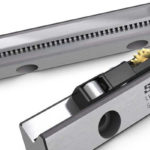
Like linear stages, goniometer stages come in a wide variety of designs, but every design incorporates a low-friction guide and a high-precision drive mechanism. The guide mechanism can be a curved dovetail bearing, a curved crossed roller guide, or even an air bearing. In some designs, bearing races are machined directly into the stage to form the equivalent of a partial, single-row rotary bearing that supports and guides the load.

goniometer
Curved crossed roller guides, also referred to as gonio ways, are often used in goniometer stages.
Image credit: Nippon Bearing Co., Ltd.

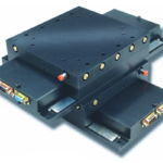
The drive mechanism can be a high-ratio worm gear, a ball screw or lead screw (typically with an anti-backlash nut), or a direct-drive motor. Because goniometers are often used for very fine positioning, worm gear versions use very high ratios — in the range of 300:1 — and can be driven by hand with a micrometer or with a stepper or servo motor. Similarly, ball and lead screw versions use very small leads, and these are often driven by servo or stepper motors. Goniometer stages with crossed roller guides and piezo motors can provide ultra-high resolution for small ranges of motion to meet the needs of micro- or nano-positioning applications.

goniometer
This large goniometer stage uses curved profiled rail guides and a precision worm gear driven by a servo motor to provide ± 45 degrees (90 degrees total) rotation.
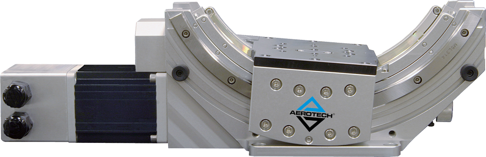
Image credit: Aerotech Inc.

One of the benefits of such a wide variety of designs is that goniometer stages can be used in a broad range of applications, including cleanrooms and vacuum environments.


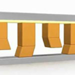
Most goniometer stages are designed to allow stacking of multiple stages, providing orthogonal rotation around a common point. And in many cases, manufacturers of goniometer stages also manufacture linear stages and have made it easy to integrate the two types from a mounting and control standpoint, presenting designers with a pre-engineered solution that provides both linear and rotational movement.

goniometer
Here, a three-axis X-Y-Z stage provides linear positioning for an assembly of two stacked goniometer stages, for a total of 5-axis motion. All stages use crossed roller guides (curved versions for the goniometers) and piezo motor drives.
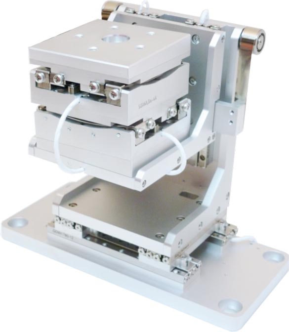
Image credit: SmarAct GmbH

Feature image credit: Newport Corporation

You may also like:


  • What’s the difference between serial kinematics and parallel kinematics in…
  • resolution
    When is resolution important for linear systems?

  • Gallery: Crossed-roller slide variations and uses
  • air bearings
    Common applications for air bearings
  • Piezo motor
    What’s the difference between a piezo actuator and a piezo…

Filed Under: FAQs + basics, Featured, Stages + gantries

Reader Interactions

Comments

  1. Brendan Shelton says

    July 30, 2019 at 8:42 am

    I appreciate that you explained what the common industrial uses for goniometer stages are, including micromachining applications and inspection systems. I didn’t quite understand goniometer stages when it was explained during class. Your article does a great job of explaining these concepts.

Leave a Reply Cancel reply

You must be logged in to post a comment.

Primary Sidebar

MOTION DESIGN GUIDES

“motion

“motion

“motion

“motion

“motion

“motion

“motion

“motion

“motion
Subscribe Today

RSS Featured White Papers

  • Identifying Best-Value Linear Motion Technologies
  • What are dual-motion hybrid actuators and where do they excel?
  • Considerations for adding Linear Guide Features to Industrial equipment

RSS Motion Control Tips

  • Miniature controllers from FAULHABER control a range of dc motors
  • Robotic bartender powered by Arduino-compatible controller and BLDC servo motors
  • What are double- and triple-stack hybrid stepper motors ?
  • PowerSTAR right angle gearmotor features advanced precision hypoid gearing
  • What are different ways to express a gear ratio?

Follow us on Twitter

Tweets by Linear_Motion

Footer

Linear Motion Tips

Design World Network

Design World Online
The Robot Report
Coupling Tips
Motion Control Tips
Bearing Tips
Fastener Engineering

Linear Motion Tips

Subscribe to our newsletter
Advertise with us
Contact us
About us

Follow us on TwitterAdd us on FacebookAdd us on LinkedInAdd us on YouTubeAdd us on Instagram

Copyright © 2021 · WTWH Media LLC and its licensors. All rights reserved.
The material on this site may not be reproduced, distributed, transmitted, cached or otherwise used, except with the prior written permission of WTWH Media.

Privacy Policy