
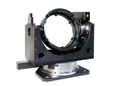
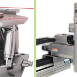
Image credit: Newport Corporation
In simple terms, a gimbal is a pivoting platform that allows an object to rotate around one or more axes. They’re often found in photography and videography applications to stabilize cameras, as well as in navigation systems for ships. In these applications, two or more gimbals are mounted together with orthogonal axes (axes mounted 90 degrees to each other), and the supported object remains stationary while the gimbals rotate around it to counter any rolling, pitching, or yawing motions that occur.
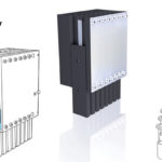
In industrial applications, gimbals are typically classified as a type of rotary stage and are also referred to as “gimbal mounts,” since they’re commonly used for mounting mirrors, sensors, or other direction-sensitive equipment. Gimbal axes are driven with servo, stepper, or even piezo or voice coil motors. For precise positioning, they operate in a closed-loop system with a feedback device — typically a high-resolution rotary encoder — on each axis.
Gimbal movements are based on the horizontal coordinates of azimuth and elevation, with some multi-axis gimbal stages also including a third axis whose movement is referred to as roll. Azimuth and elevation are most easily visualized by thinking of an object’s position relative to the horizon, as shown below.
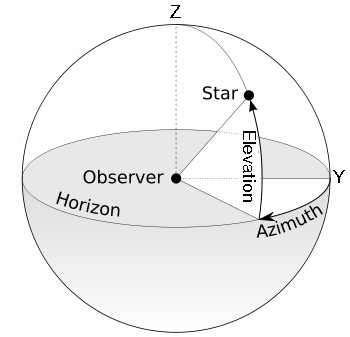
Azimuth is the position around the horizon, measured from a reference point such as true north or true south. Azimuth movements occur around the Z (vertical) axis.
Elevation is the object’s distance above or below the horizon (also referred to as altitude in astronomy and aerospace applications). Elevation movements occur around the Y axis.
Roll movements occur around the X axis as it rotates with the Y and Z axes.
To demonstrate, this video from OES Motion Control shows a three-axis gimbal system with movements in azimuth, elevation, and roll directions.
Note that some manufacturers and reference guides refer to the three axes of a gimbal stage as yaw (rather than azimuth), pitch (rather than elevation), and roll.
Gimbals can be gear-driven or direct-driven and often use radial crossed roller bearings to support the load. Rotation can be specified within a required range for each axis — for example, ± 90 degrees azimuth, ± 45 degrees elevation, and ± 90 degrees roll. When full rotation (360 degrees) is required on any axis, a slip ring can be used to transmit power and data, eliminating complex systems for managing cables as the axis rotates.
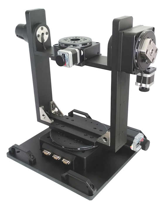
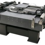
Image credit: Optimal Engineering Systems, Inc.
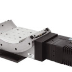
Gear-driven gimbals most often use worm gears with servo or stepper motors. A benefit of gear-driven designs is that the gear helps to mute and dampen the effects of the motor hunting for position due to overshoot or undershoot. Gear-driven designs also have higher load capacities than direct-drive gimbals, but gears introduce backlash to the system, which reduces bi-directional repeatability. This backlash, or play, also makes it difficult for the gimbal to execute quick movements, especially when changing travel direction.
Direct-drive gimbals, which use rotary torque motors, benefit from fewer mechanical connections in the drivetrain, and therefore, less backlash. Although they have lower load capacities, they’re better suited for dynamic movements and rapid changes in the direction of rotation.
Gimbals are common in aerospace and military applications, especially for tracking and communication devices. In industrial settings, two- and three-axis gimbal stages are used for sensor calibration and alignment and for precise angular positioning of optics and lasers.
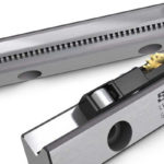
Feature image credit: Newmark Systems Incorporated

Leave a Reply
You must be logged in to post a comment.