
Ball screws are often the drive mechanism of choice in applications that require high thrust forces with excellent positioning accuracy and repeatability. But one of the drawbacks of ball screw technology is that speed is inversely related to length — the longer the ball screw shaft, the more likely it is to whip, like a jump rope, as it turns. This behavior limits the maximum travel distance that can be achieved when high speeds are necessary, and vice-versa.

What is critical speed?
The permissible operating speed of a ball screw assembly depends on two parameters — critical speed and characteristic speed. Characteristic speed is determined by factors related to the ball nut, including the ball return system and the mass of the balls. However, improvements in ball nut manufacturing and ball recirculation methods have provided most ball screw assemblies with very high characteristic speeds, so the limiting factor is typically the critical speed.
For a rotating shaft, such as a ball screw assembly, critical speed is defined as the angular velocity that excites the natural frequency, or first resonant frequency, of the assembly. If the shaft is operated at its natural frequency, it can begin to resonate, causing severe damage — or even destruction — to the assembly.
Why do ball screws experience resonance?
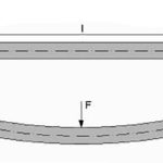
In theory, a shaft is perfectly balanced — that is, its mass is perfectly distributed about its volume — so that when it rotates, there is no bending of the shaft and the center of mass lies along the axis of rotation. But in the real world, even the most precisely manufactured and machined shafts are not perfectly balanced, so the center of mass is very slightly offset from the axis of rotation. In addition, because the screw shaft is supported only at its ends, it bends somewhat under its own weight, moving the center of mass even farther from the axis of rotation. As the ball screw shaft rotates, the discrepancy between the center of mass and the axis of rotation produces centrifugal forces, which cause the shaft to deflect, or whip, like a jump rope.
If this vibration — or ball screw whip — approaches or reaches the natural frequency of the screw shaft, resonance can ensue and lead to increased noise, damage, and, in extreme cases, yielding of the shaft.
How to calculate ball screw critical speed
The critical speed of a shaft depends on its mass, length and diameter, the amount of deflection it experiences, and the end support method (type of end bearings).
The equation for critical speed of a ball screw is:
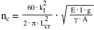
nc = critical speed (rpm)
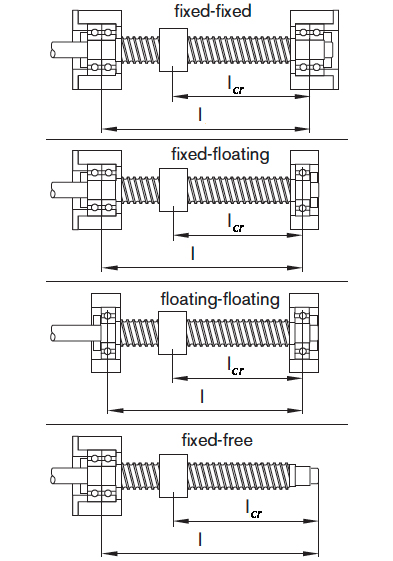
k1 = factor depending on end bearing arrangement
Lcr = unsupported length of screw shaft (mm)
E = modulus of elasticity of screw shaft (N/mm2)
I = planar moment of inertia (mm4)
g = acceleration due to gravity (mm/s2)
γ = specific weight of screw shaft (N/mm3)
A = cross-sectional area of screw shaft (mm2)
It’s important to remember that if the ball nut is preloaded, the unsupported length (Lcr) is based on the greatest distance between the ball nut and the end of the screw that will occur in operation. For non-preloaded ball nuts, the unsupported length is simply the length between bearings (l).
This equation can be simplified by combining all the non-variable components (k1, π, E, I, g, γ, and A). First, we’ll simplify the I/A component of the equation….
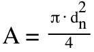
The inertia of a shaft is given as:
![]()
dn = root (minor) diameter of screw shaft (mm)
And the area is given as:
Dividing inertia by area gives us:
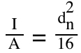
Since diameter is a variable, we’ll pull it out for now, but we need take the square root of dn2, so the variable for diameter becomes simply dn, and the 1/16 part stays within the square root.
Now we’ll define the non-variable part of the equation as “k.”
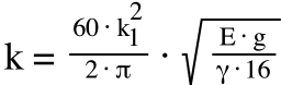
We know the values for pi (π), for the modulus of elasticity (E) and specific weight (γ) of steel, and for acceleration due to gravity (g):
π = 3.1415
E = 2.06 x 10⁵ N/mm2
γ = 7.85 x 10⁻⁵ N/mm3
g = 9.8 x 103 mm/s2
So we can determine the value of the combined variables:

![]()
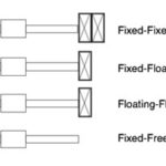
Typical values of k1 for different end bearing arrangements are as follows:
Fixed-Free: k1 = 1.875
Floating-Floating: k1 = 3.142
Fixed-Floating: k1 = 3.927
Fixed-Fixed: k1 = 4.730
Now we can construct the simplified equation for ball screw critical speed, using “k” to represent all the non-variable components.
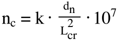
Notice that because we’re working in millimeters, the factor k is a very large number (42,000,000 for example). For the critical speed equation, k is typically expressed in scientific notation (notice the “107” factor included at the end of the equation).
Also note that some manufacturers include a safety factor of 0.8 when determining the value of k, since it’s generally recommended that a ball screw not be operated at more than 80 percent of its critical speed. The equations above do not include this 0.8 safety factor, so be sure to check if the manufacturer has included it in their published “k” values, or if it needs to be included during calculation.


Leave a Reply
You must be logged in to post a comment.