There are two instances when the terms “fixed bearing” and “floating bearing” are used in linear motion: to describe the support bearings used on ball and lead screws, and to describe linear guides mounted in parallel. And while the meanings of the terms are the same in both situations, their applications are different in each context.
Ball screw end bearings
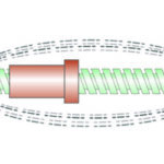
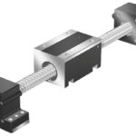
Ball screw shafts require end bearings to support radial and axial (thrust) loads caused by the moved load, process forces, and the effects of thermal expansion. This support is provided by radial bearings mounted on each end of the screw shaft.
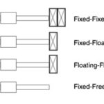
The screw end bearings can provide either fixed support, which prevents movement of the screw shaft, or floating (also referred to as simple) support, which does allow some axial movement of the screw. And in some applications, one end of the screw can be left unsupported, with no end bearing (although this is only permissible for very short screw shafts that operate at slow speeds).
When bearings are used on both ends of the screw shaft, a common arrangement is for one end of the shaft to be fixed and the other end floating. The fixed end bearing is typically an angular contact thrust bearing, and the floating end bearing is typically a single-row radial bearing.

The type of end fixity — that is, the type of end bearings used on the screw — plays a significant role in the screw’s critical speed, its permissible buckling load, and its rigidity. The more rigidly fixed the screw shaft, the higher all three values will be. However, it’s important to note the screw shafts that are rigidly fixed on both ends (with a fixed-fixed bearing arrangement) do not allow for any axial movement of the screw, which can be detrimental if the screw experiences thermal expansion.
Parallel linear guides
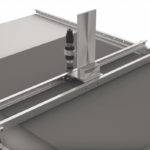
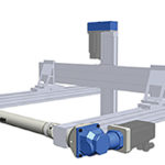
When two linear guides are mounted in parallel, with bearings on each guide connected by a rigid plate or carriage, precautions must be taken to prevent binding, or “jerky” motion that can be caused by misalignment between the rails, uneven loads on each bearing, or differences in manufacturing tolerances between rails and bearings.

Image credit: Hoerbiger Origa
One way to help prevent binding is to mount the linear guides with one guide fixed and the other guide floating. In this context, “fixed” means that one linear guide is precisely mounted, aligned, and secured — preferably with at least one machined reference edge. The second, floating, linear guide is loosely secured, while the bearings of both guides are connected by a precisely machined connecting plate, or carriage. The bearings are then traversed one or more times along the length of the guides.
Because the floating linear guide is only loosely secured to the mounting surface, as the bearings travel along its length, it can “settle in” to a position that best suits the movement of the bearings without causing them to bind. The floating guide is then securely screwed to the mounting base, and the assembly can operate without binding.
Note that the use of the fixed and floating arrangement applies not only to recirculating linear bearings, but also to plain linear bearings. In fact, the well-known “2:1 ratio,” which is most often applied to plain bearings, specifies that if two plain bearing guides are used in parallel, the linear guide closest to the cantilevered load or driving force should be fixed, and the other guide should be floating.


Leave a Reply
You must be logged in to post a comment.